CS 353 Fall 2020     Syllabus       Labs/Projects

Lab Goals Part 1: Potentiometer Part 2: Button Part 3: Motor Check-in

Lab 2: Vibrotactile Motor

Goals

  • Wire a potentiometer, and print the values to serial.
  • Wire a button in series with a resistor to turn on and off print statements using an interrupt.
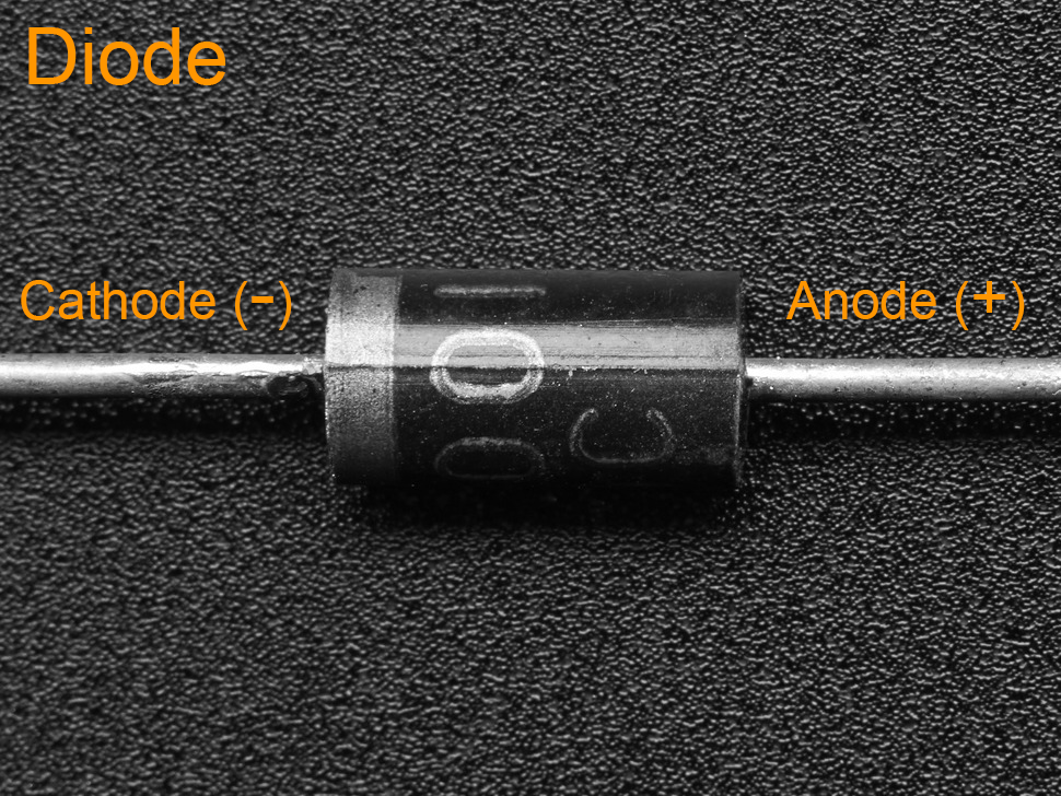
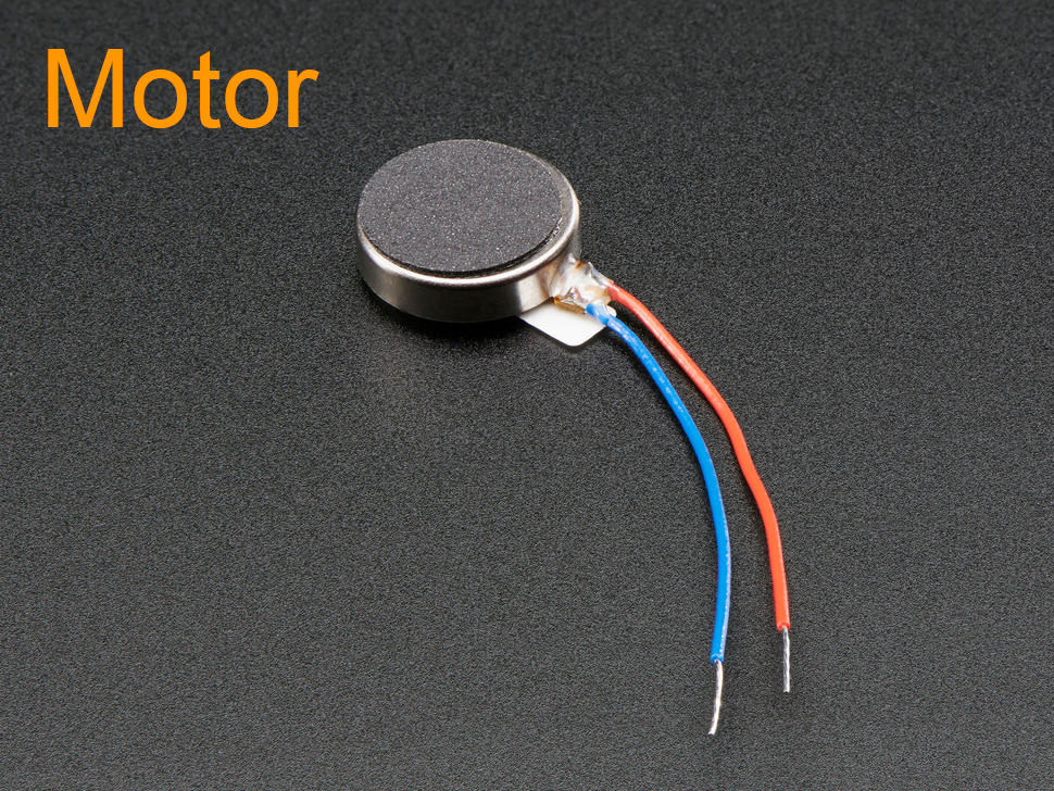
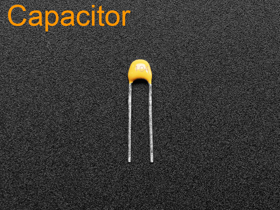
  • Wire a vibrotactile motor, in a parallel circuit with a capacitor and diode.
  • Use the potentiometer, transistor, and pulse-width modulation (PWM) to control the speed of the motor.

Part 1: Potentiometer

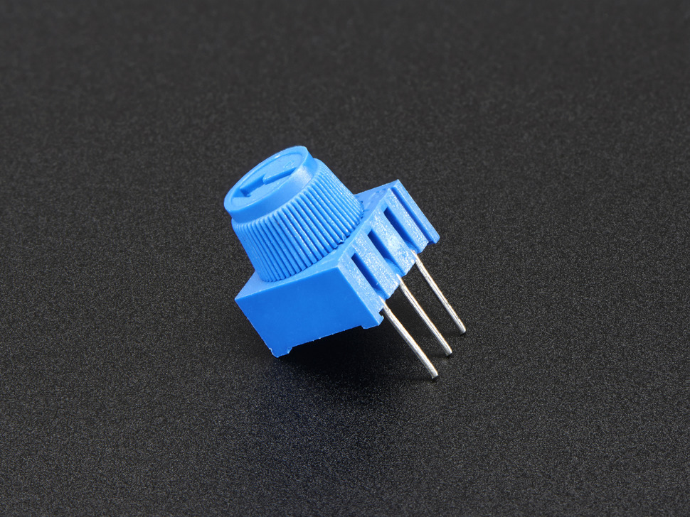
Potentiometer

A potentiometer is a resistor that controls an adjustable voltage divider (aka potential divider). Using a knob it controls how much output voltage it provides.

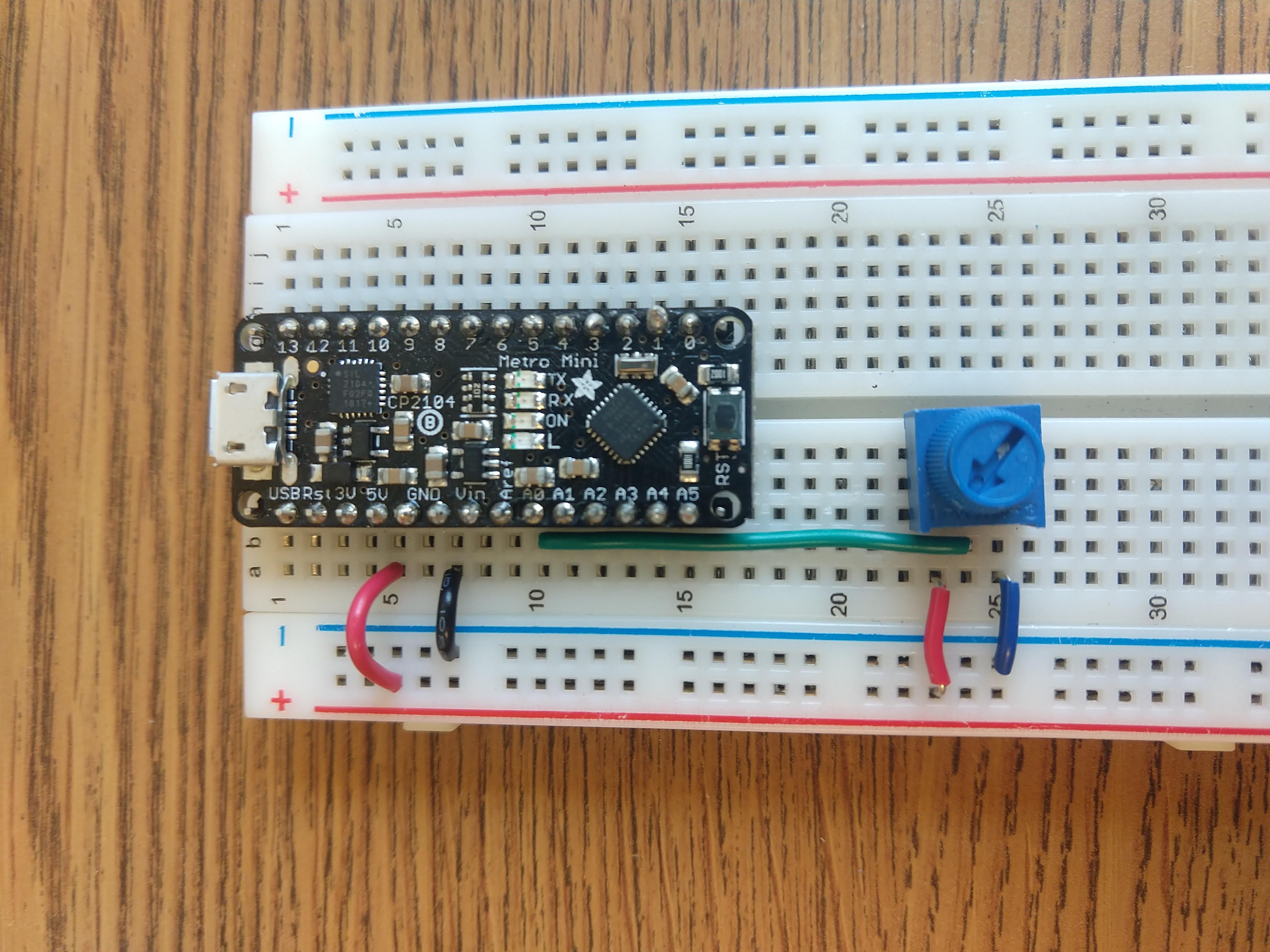
Build the circuit

Italian Trulli
  1. Connect the central pin to A0.
  2. Connect 1 of the outer pins to ground (negative) and the other outer pin to power (5V).

Program the Arduino

  1. Program your Arduino to read from A0 and print the signal to Serial.
  2. Turn the knob of the potentiometer, and the values should change.
  3. What happens if you switch which outer pin is connected to ground and power?


Italian Trulli Italian Trulli

Part 1: Button

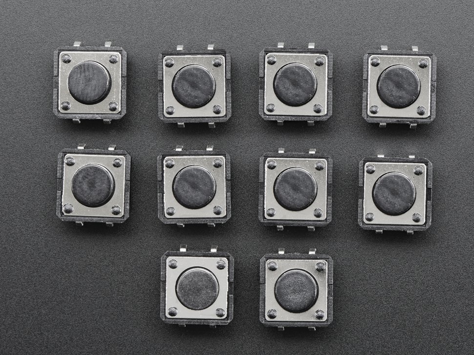
Button

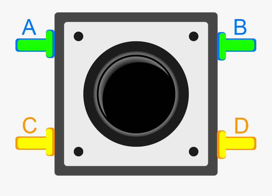
A button or a switch is a device that can connect and disconnect electrical current. In the image to our right pins C and D are connected and A and B are connected. When the button is pressed, all pins are connected.

Build the circuit

Italian Trulli Italian Trulli

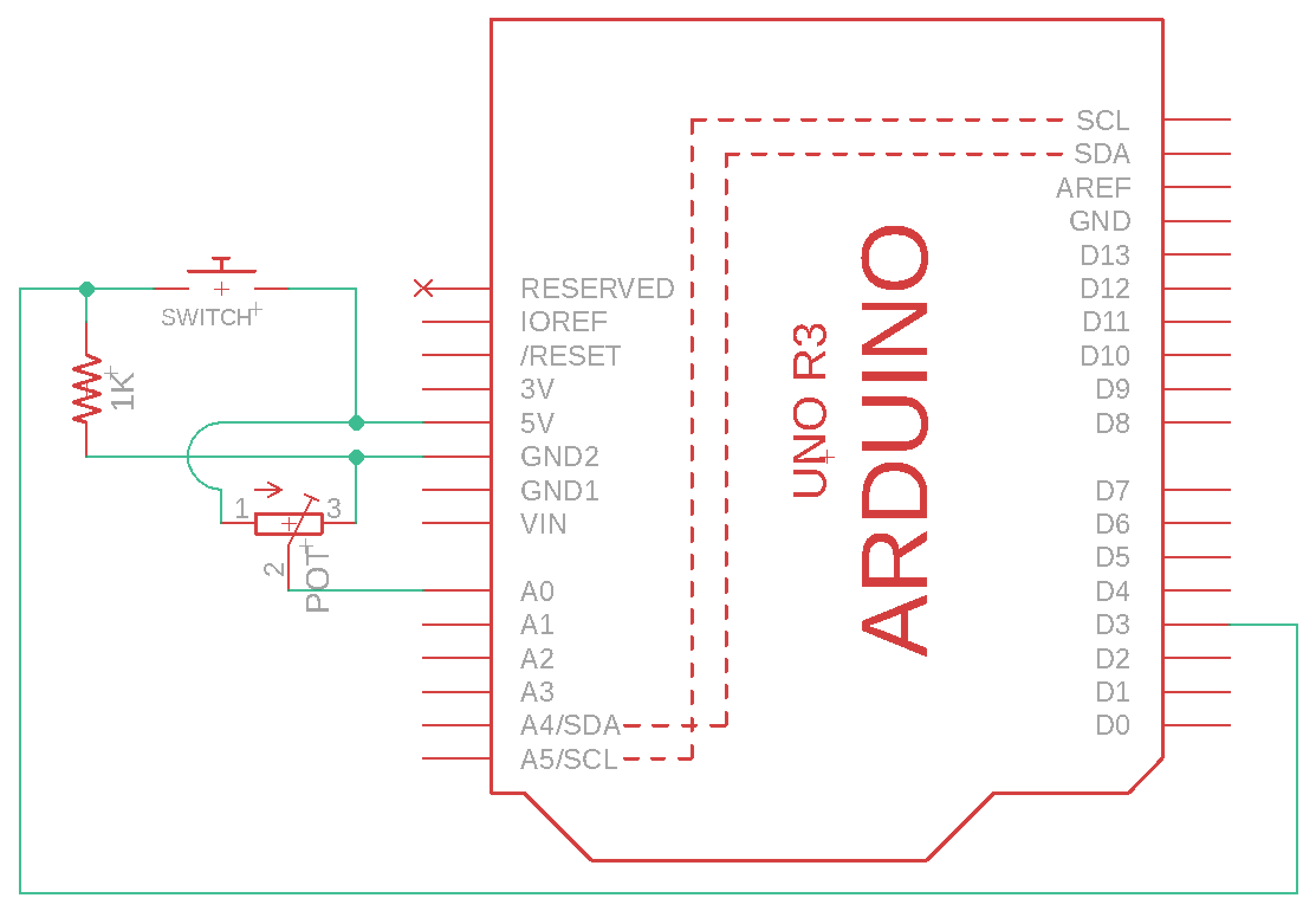
In the wiring diagram green lines that have a dot at the junction are connected. Green lines that that have an arc at a junction are not connected.

Wiring:
  1. Connect C/D to power.
  2. Connect A/B to digital input pin 3.
  3. Connect A/B to a resistor which is connected to ground.

Program the Arduino

Modify your code to use an interrupt so that a button press turns on and off reading the potentiometer and writing to serial. Follow the instructions in the Arduino documentation on how to use an interrupt.

Italian Trulli Italian Trulli

Part 1: Vibrotactile Motor

Vibrotactile Motor

In this example we are controlling the current of a motor so that it can vibrate at different speeds.

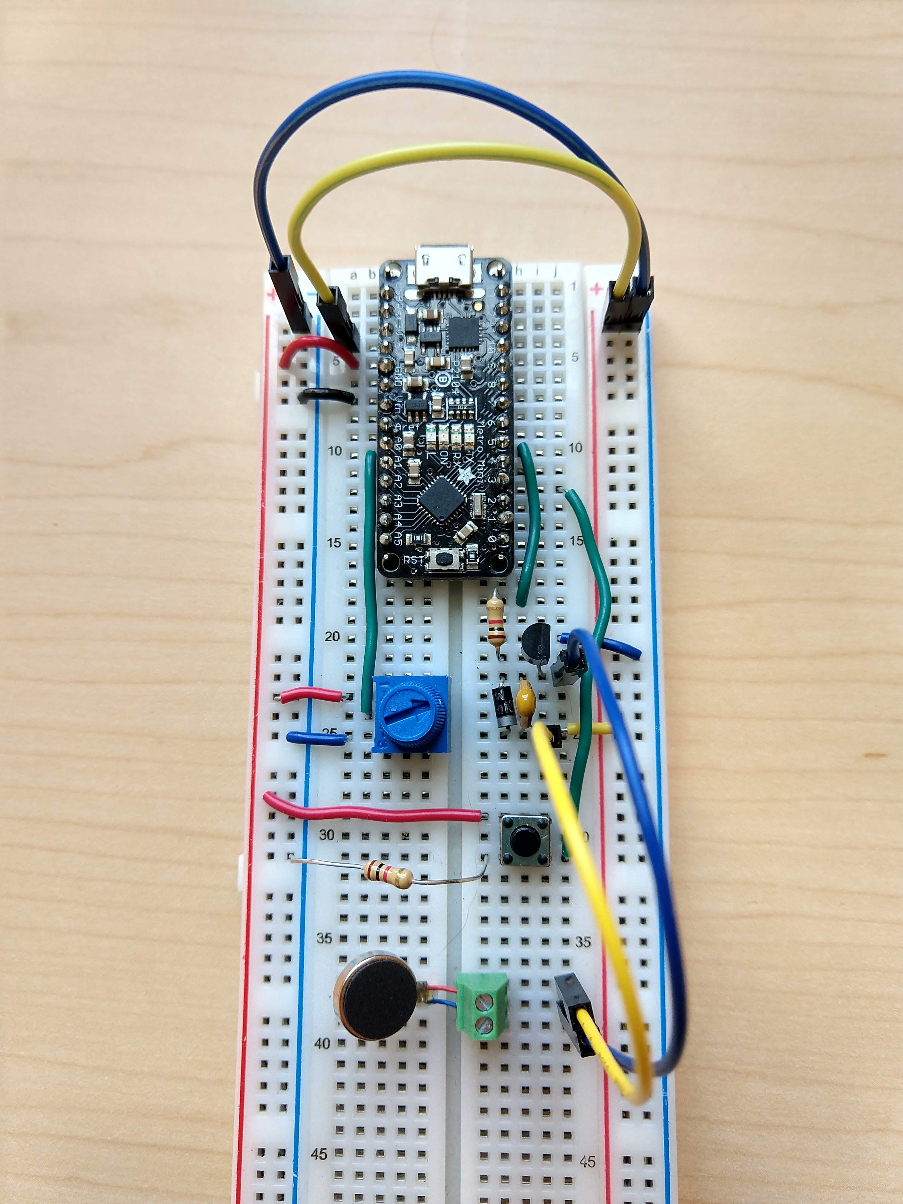
The transistor (2N2222) can provide current amplification. By wiring the output signal of the PWM pin 5 to the base of the transistor, we can control amount of current that is supplied to the emitter pin which we have connected to the cathode of the motor, the anode of the diode and one end of the capacitor.

We connect the capacitor and diode in parallel with the motor protect the transistor from voltage spikes the the motor produces. We connect the diode in reverse bias (eg cathode of motor with anode of the diode), because a diode only allows electrons to flow from negative to positive.

Here are great instructions on how to wire a motor with a transistor, capacitor and diode.
Italian Trulli Italian Trulli Italian Trulli Italian Trulli Italian Trulli


Build the circuit

  1. Connect the 2 pin pitch terminal block to the breadboard. link
  2. Use a screw driver to connect the motor leads to the 2 pin pitch terminal block. link
  3. Wire the motor, diode and capacitor so they are in a parallel circuit. Connect the anode of the diode to the motors red wire and 1 side of the capacitor. Connect the cathode of the diode to the motors red wire and 1 side of the capacitor.
  4. Connect the postive side of the motor, diode and capacitor to 3V.
  5. Connect the emitter pin (E) of the transistor to the negative side of the motor, diode and capacitor.
  6. Connect the base pin (B) of the transistor to a 1K resistor in series, and connect the other end of the resistor to digital pin 5.
  7. Connect the collector pin (C) of the transistor to ground.

Program the Arduino

Modify your code so that the potentiometer value controls the intensity of the vibration and the button turns on and off the motor. You will have to map the potentiometer range (0-1023) to the transistor range (0-255) and write it to digital pin 5. Delay 100 microseconds at the end of the loop.
Italian Trulli Italian Trulli

Check-in

Check-in

The goal is for you to have the Vibrotactile Motor working by the check-in. It's okay if you don't, just submit a check-in (video&doc) of what you have done so far and you'll receive 75% on the check-in (-5% of your project grade). You can only turn in extensions if your check-in is complete.

Submit a video and Check-in document on Google Classroom

Upload a 0.5-2 minute Documentation Video with narration.
  • Show that you can change the intensity of the vibration with the potentiometer.
  • Show that you can turn on and off the signal by pressing the button.
  • Say what you are doing while you are doing it like: "I am changing the intensity of the vibration with the potentimeter", "I can turn on and off the vibrating motor with a button".
Attach a Google Doc Check-in which includes:
  • Photo of circuit:
    • Clear photo of the circuit in which the wiring is clearly visible, wired correctly.
  • Video Description Paragraph:
    • 5-10 sentences describing what is happening in the video.
    • If complete: How does it work?
    • If incomplete: What is the current issue? Where are you stuck?
  • Project Idea:
    • 5-10 sentences describing an idea for a project that incorporates both the IR sensor and vibrating motor. (Button, potentiometer, and red LED are optional).
    • What is it?
    • What niche is it designed to fill?
    • What materials would you need?
    • How would you implement it?