Lab 5a: Sound Meter |
Goals
- Design a circuit based on component specifications.
- Wire components based on self-drafted circuit design.
- Use a timer to calculate the amplitude of a signal over a window.
|
Part 1: Design Circuit |
Design Your Circuit
Draw a circuit diagram representing your RGB LED and microphone wired to the Arduino.
RGB LED - Common Cathode
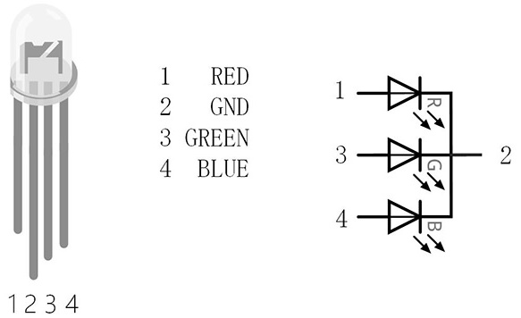
- Using the datasheet, figure out which pin is the common cathode.
- Calculate required resistance for each anode pin. Include calculations in your lab report. Use the LED's forward voltage and forward current from the datasheet.
- Equations:
- Vresistor = Iresistor * Rresistor
- Vpower = VLED + Vresistor
- Figure out which pins of the Arduino you can use analogWrite() with.
Do not use Pins 9 and 10 because we will be using timer1 for the microphone.
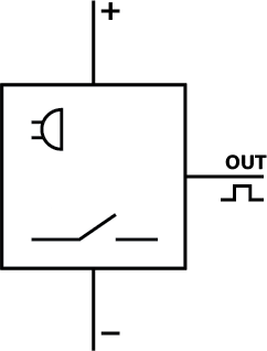
Microphone
- Connect VCC to the Arduino's 3.3V supply.
- Connect GND to the Arduino's ground. Use a different ground pin on the Arduino for the RGB LED and the microphone.
- Connect OUT to an analog input pin.
|
Part 2: Microphone |
Wire the Microphone
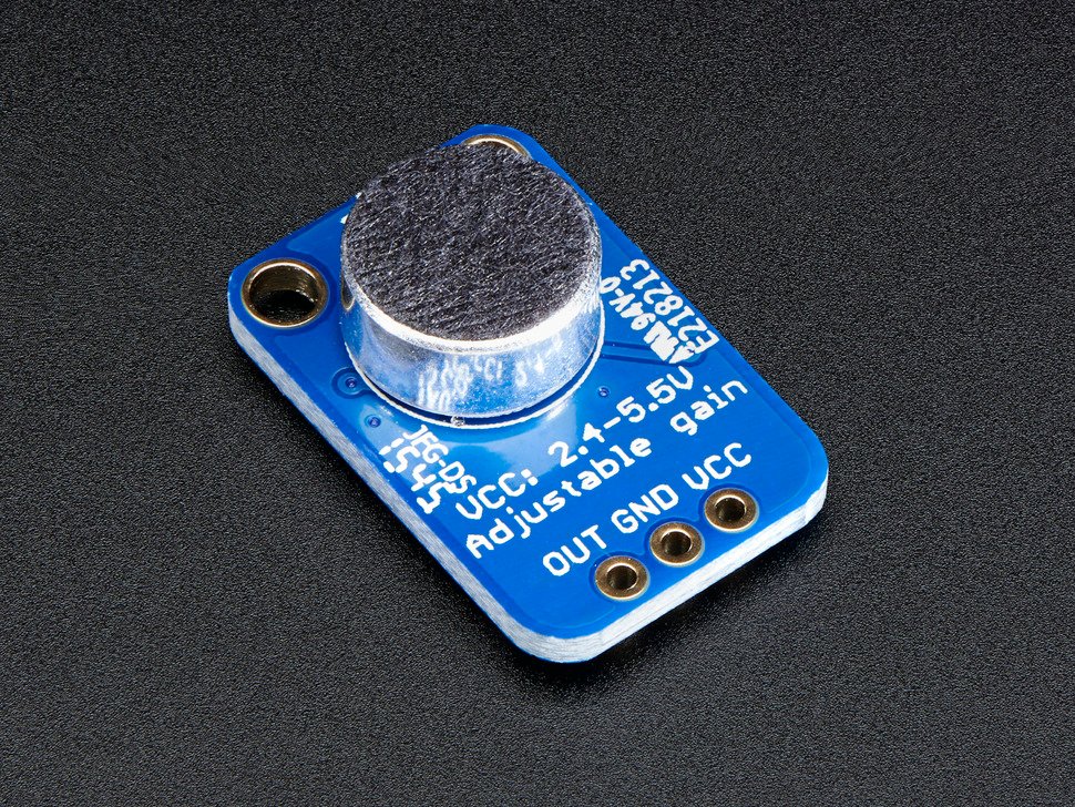
Wire your microphone to your circuit based on your circuit diagram.
Test the Microphone
Read from the microphone pin and write the value to the Serial port. Is it working?
Find Microphone Min and Max values over a 128ms Window
- Using the ATmega datasheet, with registers setup timer 1 as a CTC timer with a prescalar of 64.
- With registers, enable the timer compare interrupt.
- Set the compare match register (ORC1A) to [ Arduino clock speed / (prescaler * desired interrupt frequency) ] - 1.
- The Arduino clock speed is 16 megahertz.
- Call the interrupt every 1ms.
- 1 second is equal to 1 hertz frequency.
ISR(TIMER1_COMPA_vect){}, will be called every 1 millisecond. We want to find the minimum and maximum microphone readings over a 128 millisecond window. Ignore any spurious readings >= 1024. When the 128ms window is complete, calculate the peakToPeak (maximum-minimum), and reset the maximum, minimum and count. - Test the system, by printing peakToPeak in the loop to the serial port and see how it responds to different volume levels.
|
Part 3: RGB LED |
Wire the RGB LED
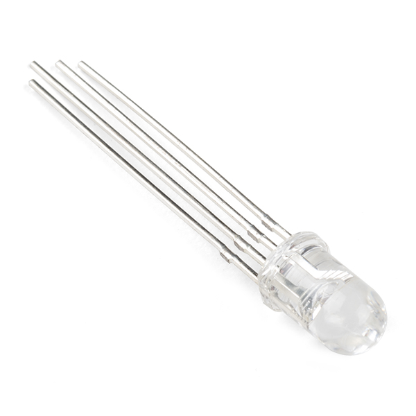
Wire your RGB LED to your circuit based on your circuit diagram.
Test the RGB LED
- Using registers (Port Registers & Pin Mapping) set the R, G and B pins to OUTPUT.
- Write 255 to each pin individually to confirm which is which.
Program the circuit
Modify the loop so that the color of the LED responds to the peakToPeak value.
|
Check-in |
Check-in
The goal is for you to have the microphone and LED sound meter working by the check-in. You can only turn in extensions if your check-in is ontime and complete.
Submit a video and Check-in document on Google Classroom
Upload a 0.5-2 minute Documentation Video with narration.
- Show that you can calculate volume and print it to the terminal.
- Show that that LED responds to different audio levels with blue, green, yellowish and red.
- Describe what is happening.
Attach a Google Doc Check-in which includes:
- Documentation of the circuit:
- Resistance calculations for R, G and B.
- Drawing of the circuit you designed.
- Clear photo of the circuit in which the wiring is clearly visible, wired correctly.
- Video Description Paragraph:
- 5-10 sentences describing what is happening in the video.
- If complete: How does it work?
- If incomplete: What is the current issue? Where are you stuck?
- Project Idea:
- 5-10 sentences describing an idea for a project that incorporates the microphone with the piezo element, IR sensor and/or the vibrating motor. (Button, potentiometer, and red LED are optional).
- What is it?
- What materials would you need?
- How would you implement it?
|