Lab 2: Vibrotactile Motor |
Goals
|
|---|---|
Part 1: Potentiometer |
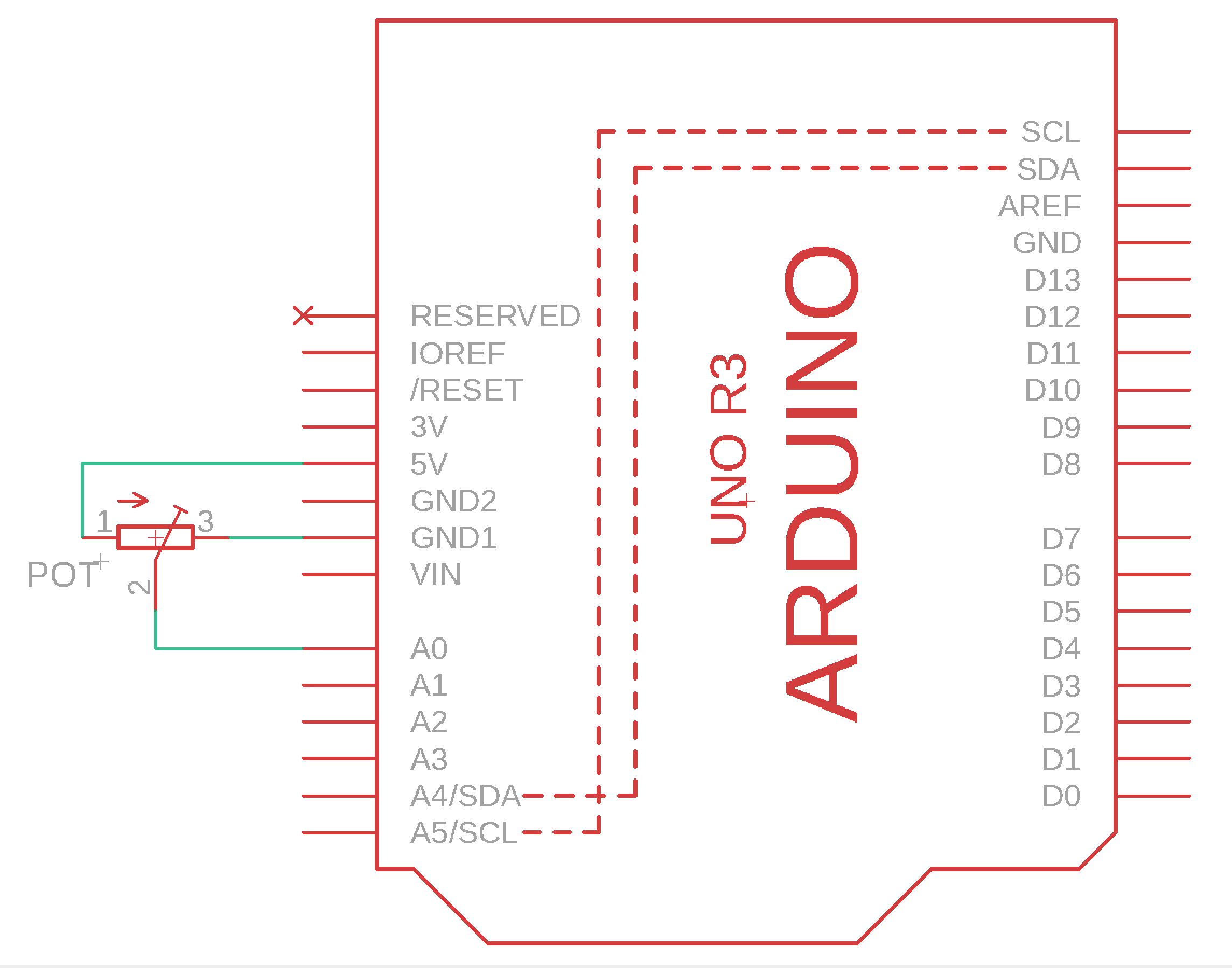
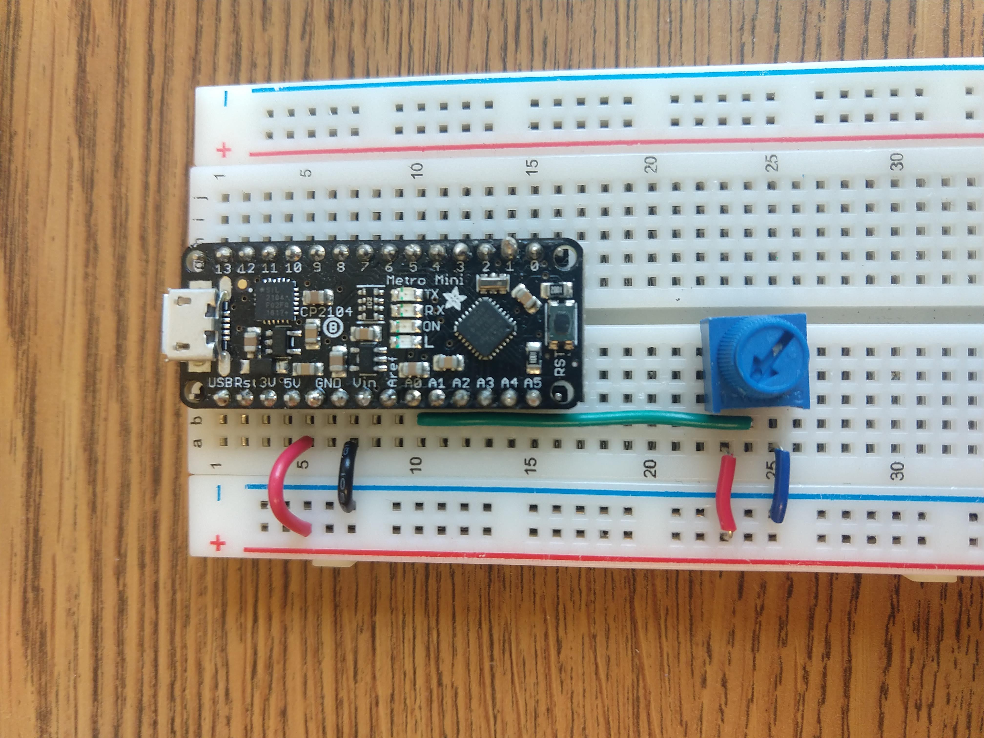
PotentiometerA potentiometer is a resistor that controls an adjustable voltage divider (aka potential divider). Using a knob it controls how much output voltage it provides.Build the circuit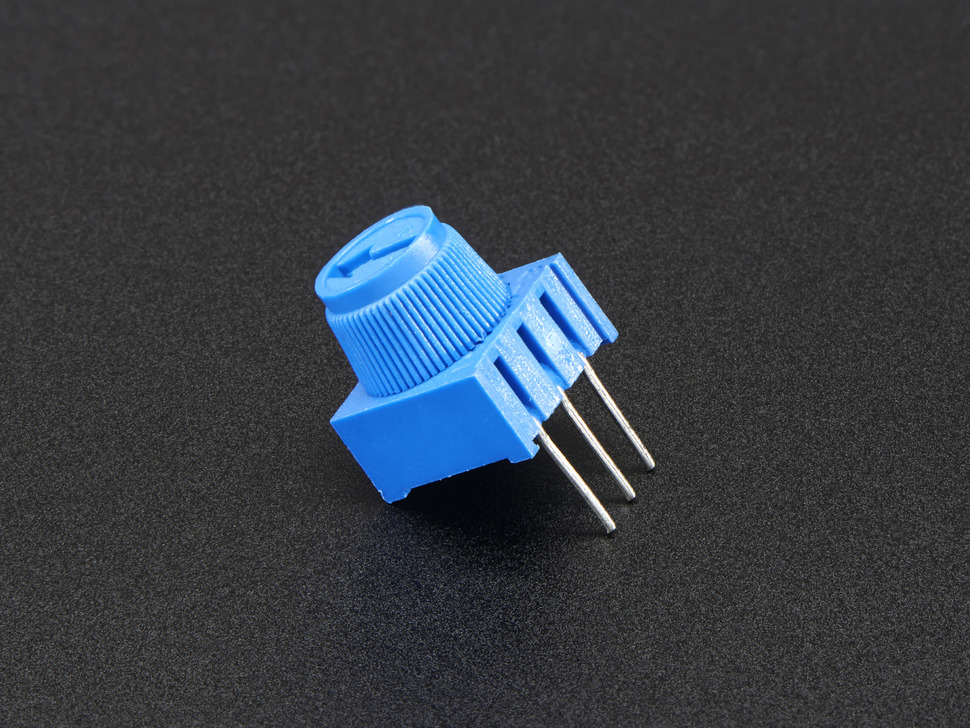
Program the Arduino
|
Part 2: Button |
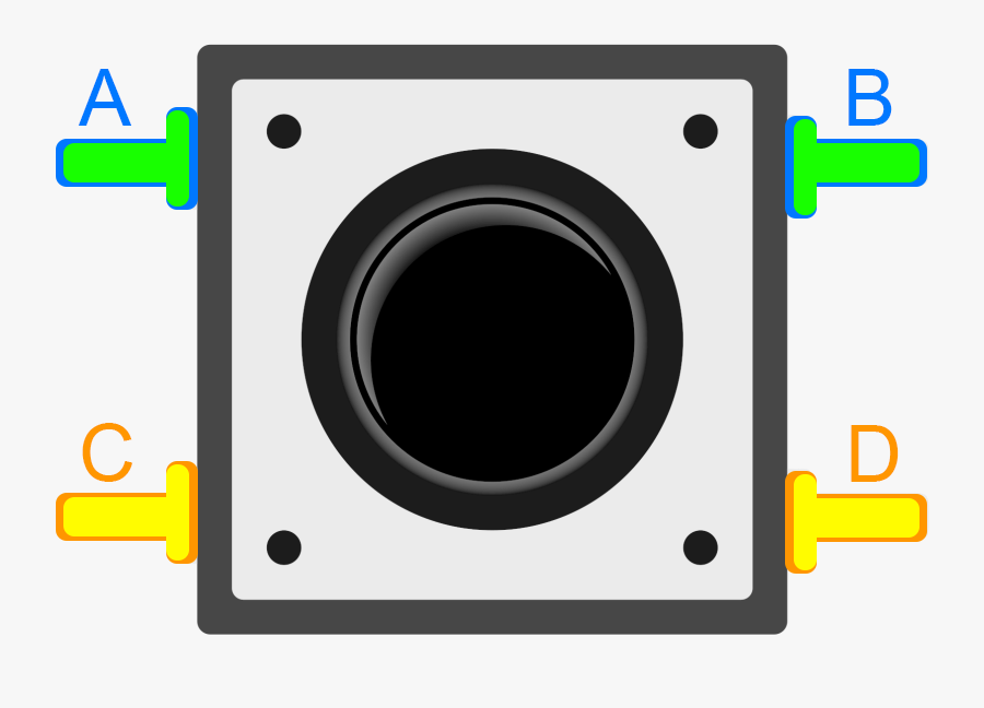
ButtonA button or a switch is a device that can connect and disconnect electrical current. In the image to our right pins C and D are connected and A and B are connected. When the button is pressed, all pins are connected.Build the circuit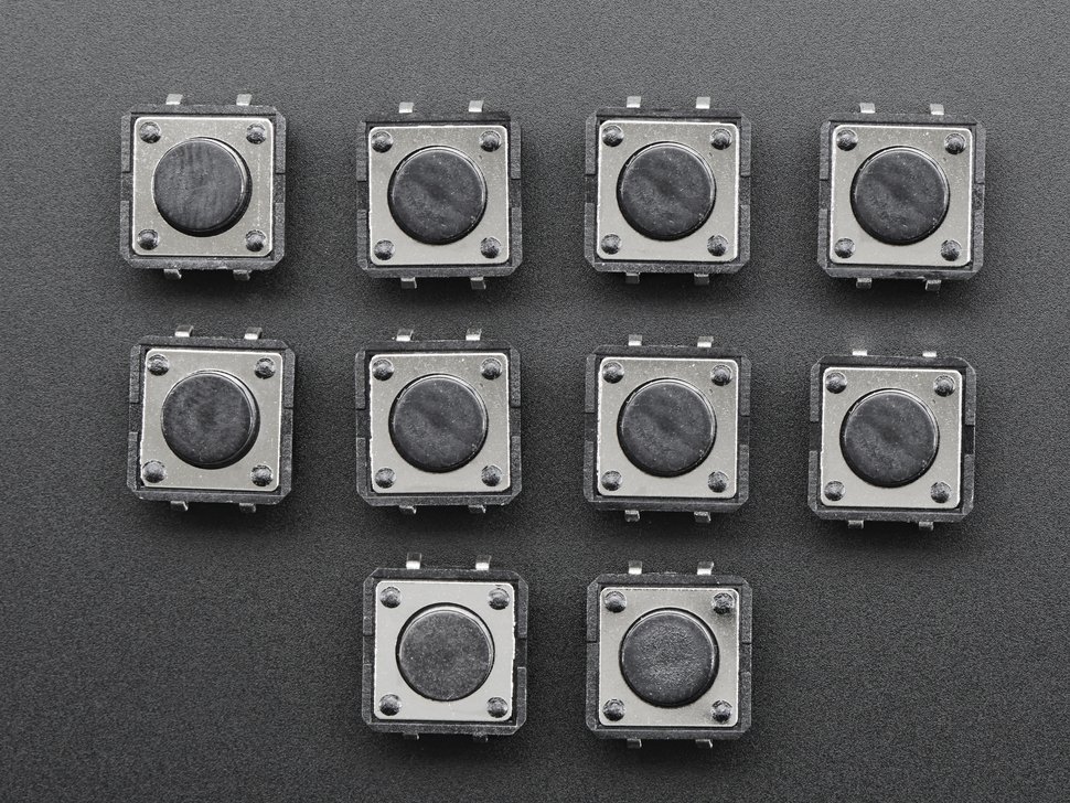
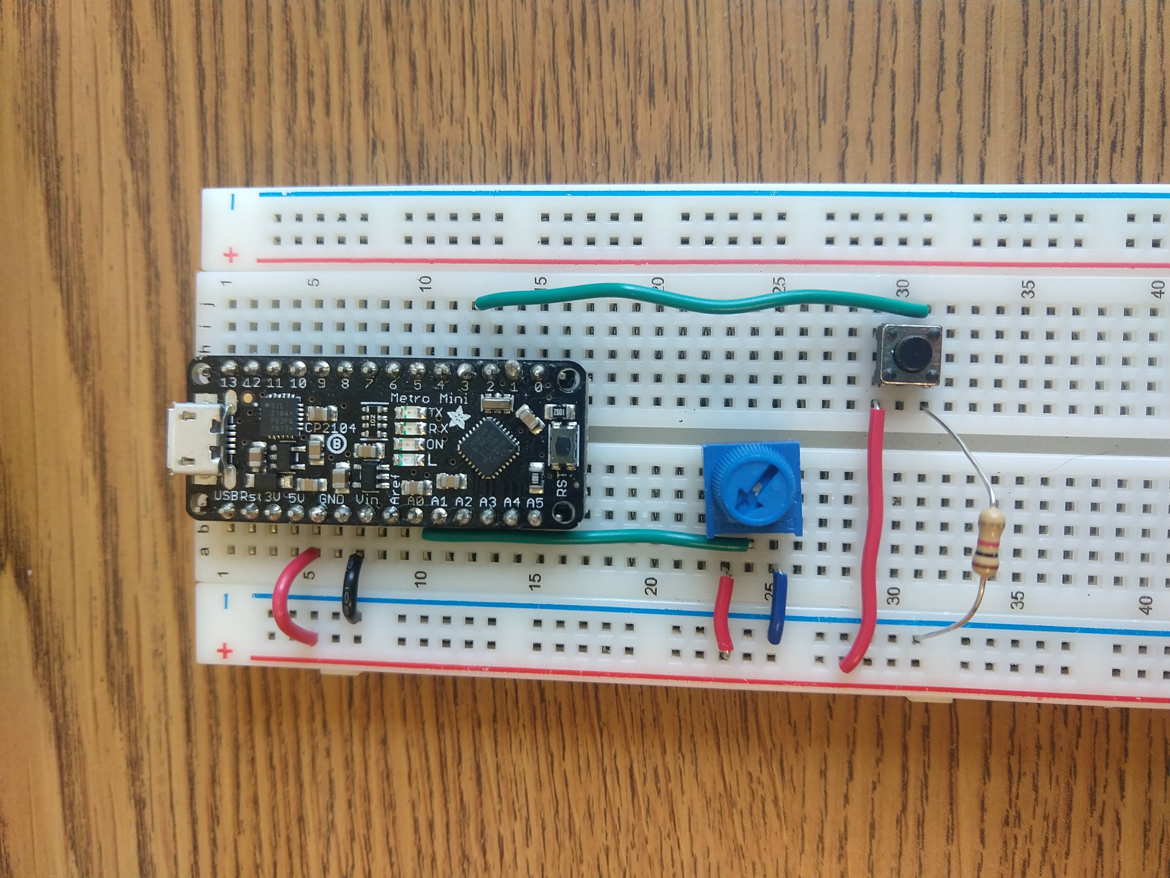
In the wiring diagram green lines that have a dot at the junction are connected. Green lines that that have an arc at a junction are not connected. Wiring:
Program the ArduinoModify your code to use an interrupt so that a button press turns on and off reading the potentiometer and writing to serial. Follow the instructions in the Arduino documentation on how to use an interrupt.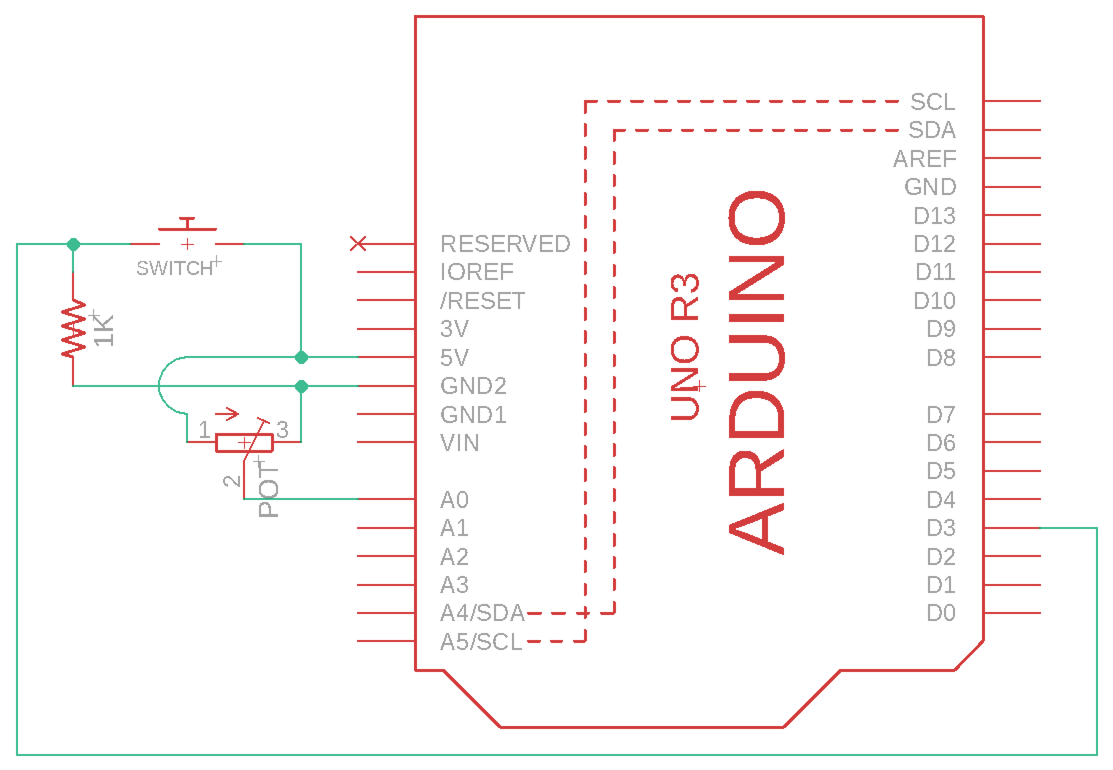
|
Part 3: LED |
LEDIn this example we are controlling the current of an LED so that it can dim and get brighter. The transistor (2N2222) can provide current amplification. By wiring the output signal of the PWM pin 5 to the base of the transistor, we can control amount of current that is supplied to the emitter pin which we have connected to the cathode of the motor, the anode of the diode and one end of the capacitor. We connect the LED in series with the 100ohm resistor. Connect the emitter pin (E) of the transistor to the negative LED lead. The positive lead of the LED should be connected to one wire of the resistor and the other wire of the resistor should be connected to 3V. 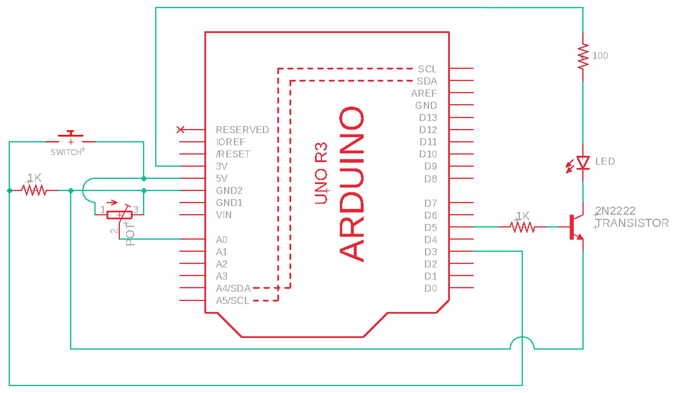
Build the circuit
Program the ArduinoModify your code so that the potentiometer value controls the brightness of the LED and the button turns on and off the LED. You will have to map the potentiometer range (0-1023) to the transistor range (0-255) and analog write it to digital pin 5. Delay 100 microseconds at the end of the loop. |
Part 4: Vibrotactile Motor |
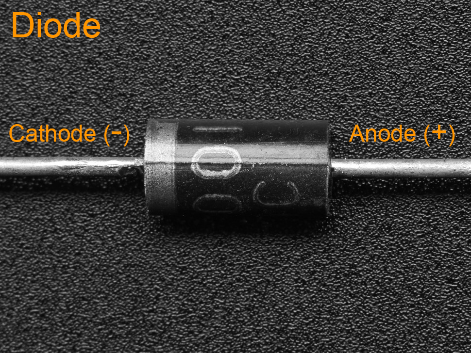
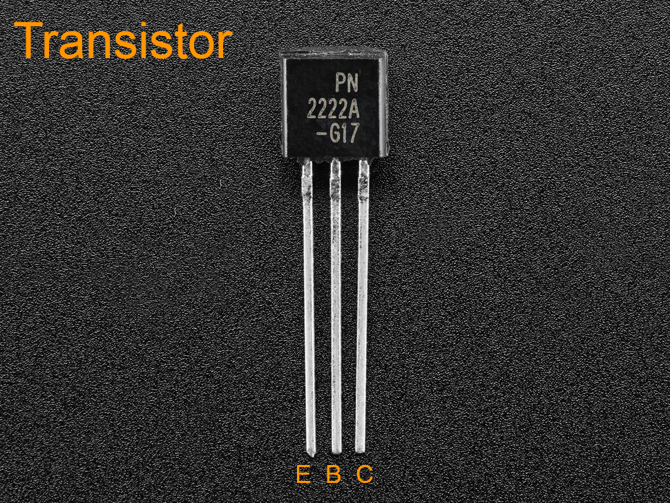
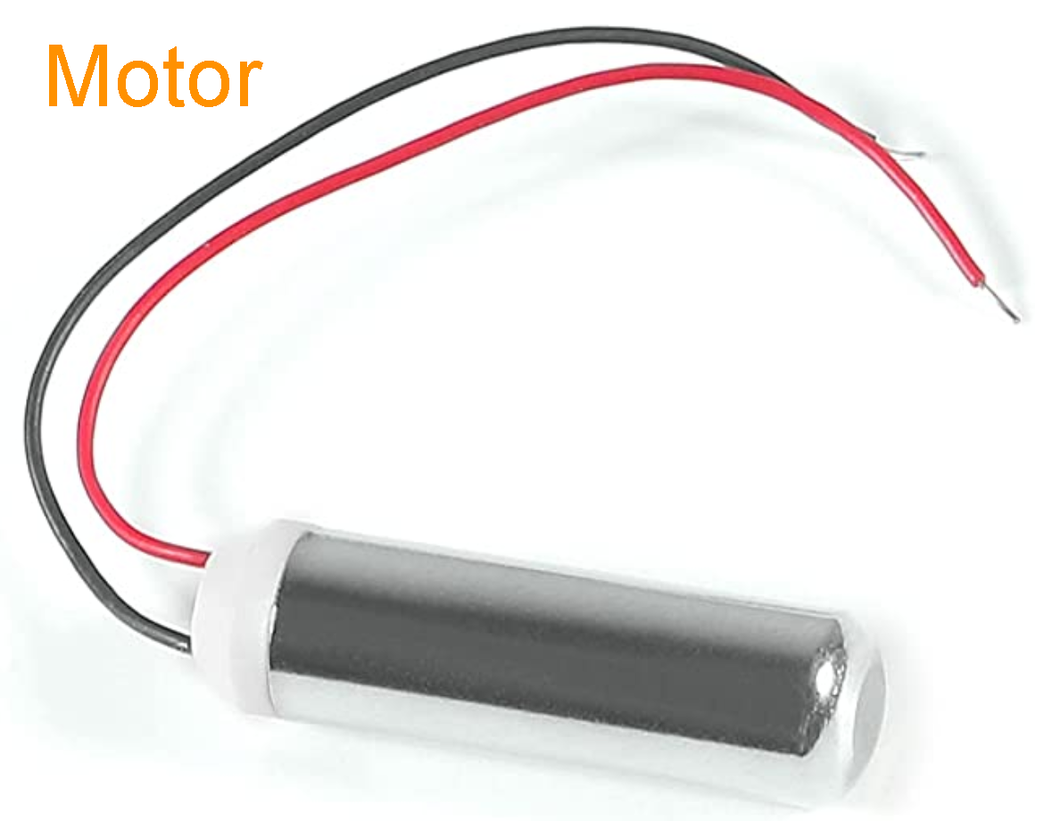
Vibrotactile MotorIn this example we are controlling the current of a motor so that it can vibrate at different speeds. We are replacing the LED with the motor. The transistor (2N2222) can provide current amplification. By wiring the output signal of the PWM pin 5 to the base of the transistor, we can control amount of current that is supplied to the emitter pin which we have connected to the cathode of the motor, the anode of the diode and one end of the capacitor. We connect the capacitor and diode in parallel with the motor protect the transistor from voltage spikes the the motor produces. We connect the diode in reverse bias (eg cathode of motor with anode of the diode), because a diode only allows electrons to flow from negative to positive. Here are great instructions on how to wire a motor with a transistor, capacitor and diode. 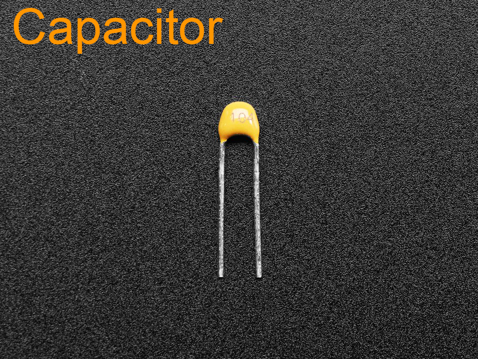

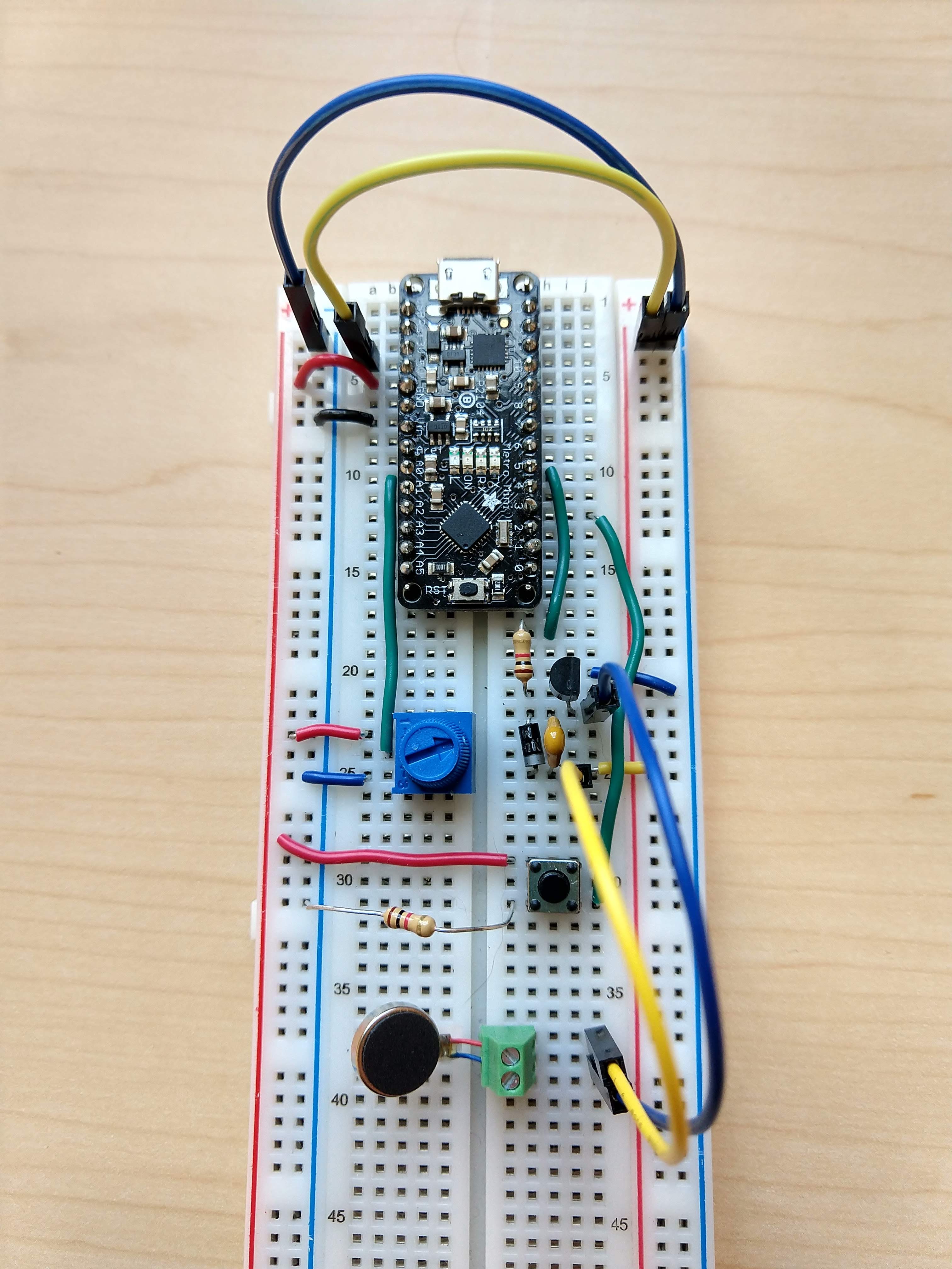
Build the circuit
Program the ArduinoThe code that you wrote for the LED should transfer to the motor, so that the potentiometer value controls the intensity of the vibration and the button turns on and off the motor.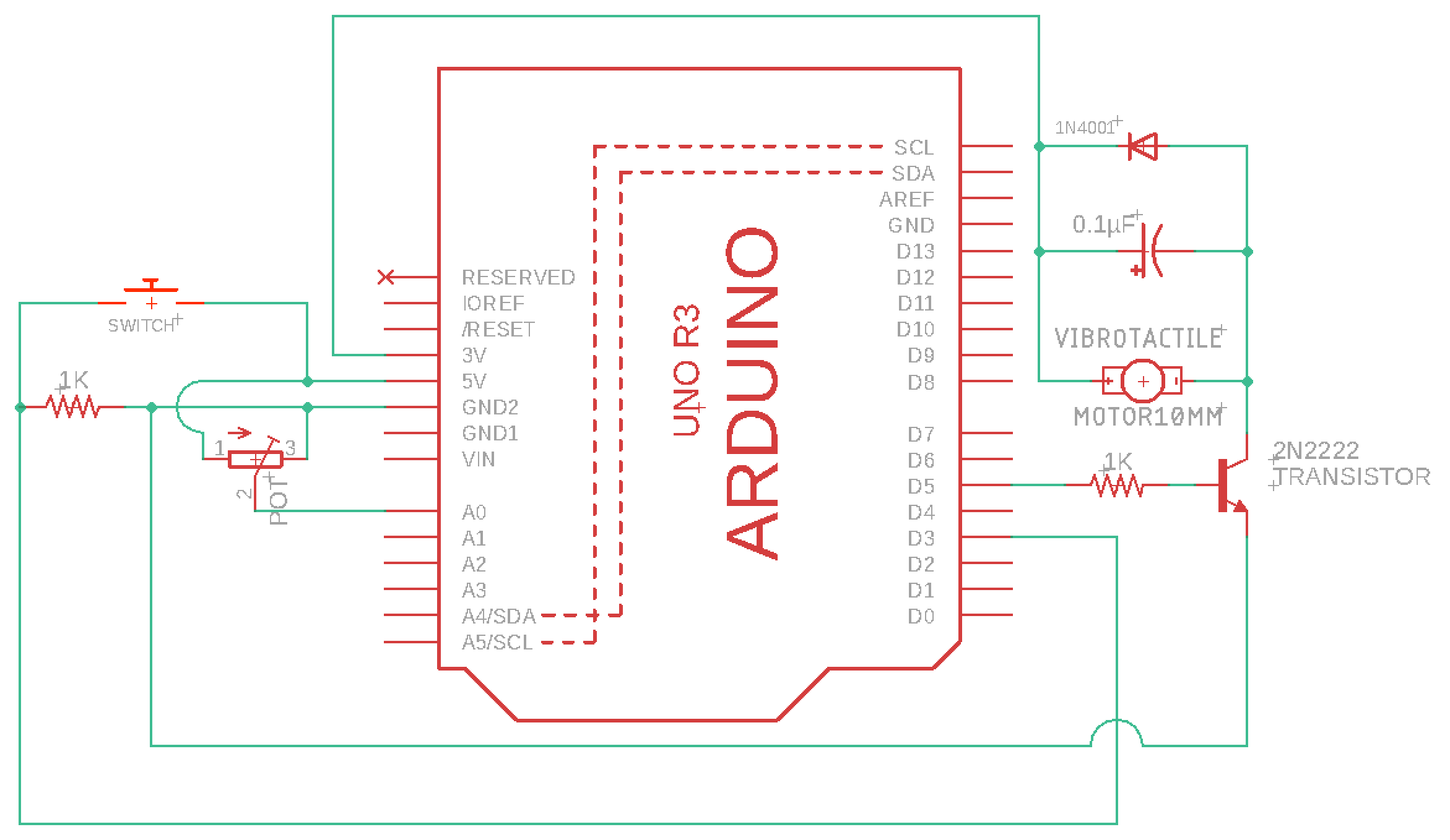
|
Check-in |
Check-inThe goal is for you to have the Vibrotactile Motor working by the check-in. It's okay if you don't, just submit a check-in (video&doc) of what you have done so far and you'll receive 75% on the check-in (-5% of your project grade). You can only turn in extensions if your check-in is complete.Submit your code on FilerSubmit your arduino code in a folder titled Submit a video and Check-in document on Google ClassroomUpload a 0.5-2 minute Documentation Video with narration.
|